
SparkFun's Qwiic Connect System uses 4-pin JST connectors to quickly interface development boards with sensors, LCDs, relays and more. site ![]()
YOUTUBE x0RDEHqFIF8 Published on May 3, 2019.
Frequently Asked Questions
Check below to answer any questions you may have about using the Qwiic Connect System.
How much power can I use?
The very conservative max current on a Qwiic cable is 226mA[1]. If you want to push it, 28AWG is good for up to 1.4A for chassis wiring “isolated, unbundled wire in free air, as per the Handbook of Electronic Tables and Formulas for American Wire Gauge.” We wouldn’t recommend pushing the cables to 1.4A, but hundreds of mA should be fine.
What’s the pinout again?
All Qwiic cables have the following color scheme and arrangement:
- Black = GND
- Red = 3.3V
- Blue = SDA
- Yellow = SCL
What about the INT pin?
We deliberately chose four conductors to increase usability of the interconnecting cables, minimize the cost of the connectors and limit the PCB footprint. All boards with extra pin options (such as interrupts, address selection, power save mode, etc.) will have those pins broken out to 0.1" holes, so the end user can add extra connections as needed.
How far can I run the Qwiic system?
I2C stands for inter-integrated circuit, and we’ve got a tutorial dedicated to it here. The bus was designed to communicate between ICs on a printed circuit board, so it wasn’t really designed to go long distances. That said, we’ve successfully communicated with sensors and boards via I2C over 1 meter (~4 ft).
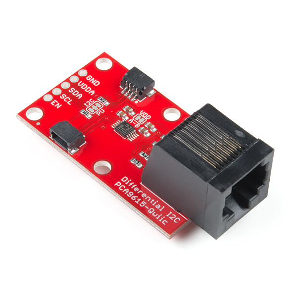
The fastest and easiest way to extend the range of your I2C communication bus is to use the Differential I2C Breakout. The breakout uses NXP’s PCA9615 IC, which converts the two default I2C signals into four differential signals, two for SCL and two for SDA. The differential signals are sent over an Ethernet cable, which attaches to the breakout through the on-board RJ-45 connectors. The differential signaling allows the I2C signals to reach distances of up to 100ft while still maintaining their signal integrity!
Can I use Qwiic on my system?
Absolutely. We would be thrilled if you used a Qwiic connector on your board or product! You can use the name Qwiic without royalties or attribution.
The requirements to say that your board is Qwiic or Qwiic-Compatible:
- You must use a version of our registered Qwiic logo from the files provided. Download Qwiic Logos
- You must use the same style 4-pin connector, JST or equivalent; you may not use a 5-pin or a different size connector. This is to make all Qwiic boards and systems interoperable.
- Boards must be 3.3V. You may do an on-board buck or boost to get to a different voltage (1.8V or 5V, for example), but the board must have onboard translation circuitry to work at 3.3V.
- All cables must follow the same color scheme: black for GND, red for 3.3V, blue for SDA, yellow for SCL.
- For obvious compatibility reasons you must follow the same pinout: GND / 3.3V / SDA / SCL.
- You may have any number of Qwiic connectors on a board. We encourage having a second connector on input and output boards to support daisy-chaining, but it is not required.
What about my 5V board?
We may implement a DC buck/boost board in the future, but for now Qwiic only supports 3.3V boards. Currently over 90 percent of our I2C products are 3.3V, and the technology market is accelerating this trend.
How can I connect existing SparkFun I2C Boards?
What if you already have a handful of SparkFun sensors and parts? We have been putting our standard GND/VCC/SDA/SCL pinout on all our I2C boards for many years. This makes it possible to attach a Qwiic Adapter that will get your SparkFun I2C sensor or actuator onto the Qwiic system.
Here is the list of the boards that have the standard I2C pinout and will work with the Qwiic adapter board: